Back جريدة مسننة Arabic Зъбна рейка Bulgarian Cremallera (mecànica) Catalan Zahnstange German Dentorelo Esperanto Cremallera (mecanismo) Spanish Kremailera (mekanismoa) Basque Crémaillère French रैक और पिनियन गियर Hindi Mehanizam sa zupčastom letvom Croatian
This article needs additional citations for verification. (November 2023) |

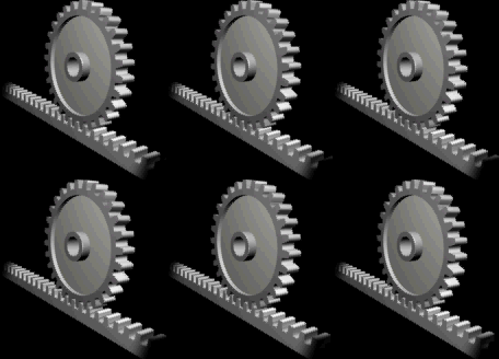
A rack and pinion is a type of linear actuator that comprises a circular gear (the pinion) engaging a linear gear (the rack). Together, they convert between rotational motion and linear motion. Rotating the pinion causes the rack to be driven in a line. Conversely, moving the rack linearly will cause the pinion to rotate. A rack-and-pinion drive can use both straight and helical gears. Though some suggest helical gears are quieter in operation, no hard evidence supports this theory. Helical racks, while being more affordable, have proven to increase side torque on the datums, increasing operating temperature leading to premature wear. Straight racks require a lower driving force and offer increased torque and speed per fraction of gear ratio which allows lower operating temperature and lessens viscal friction and energy use. The maximum force that can be transmitted in a rack-and-pinion mechanism is determined by the torque on the pinion and its size, or, conversely, by the force on the rack and the size of the pinion.
For example, in a rack railway, the rotation of a pinion mounted on a locomotive or a railroad car engages a rack, usually placed between the rails, and helps to move the train up a steep gradient.
For every pair of conjugate involute profile, there is a basic rack. This basic rack is the profile of the conjugate gear of infinite pitch radius (i.e. a toothed straight edge).[1]
A generating rack is a rack outline used to indicate tooth details and dimensions for the design of a generating tool, such as a hob or a gear shaper cutter.[1]
- ^ a b Gear Nomenclature, Definition of Terms with Symbols. American Gear Manufacturers Association. 2005. p. 72. ISBN 1-55589-846-7. OCLC 65562739. ANSI/AGMA 1012-G05.
© MMXXIII Rich X Search. We shall prevail. All rights reserved. Rich X Search